Understanding CAN Bus Communication: 7 Key Points
In a vehicle, the engine, transmission, and braking controllers can share a communication network. Understanding CAN bus means connecting the electrical signals on its wires with the messages those signals carry.
- One network, multiple controllers: Messages are broadcast, and each controller can filter the messages it needs.
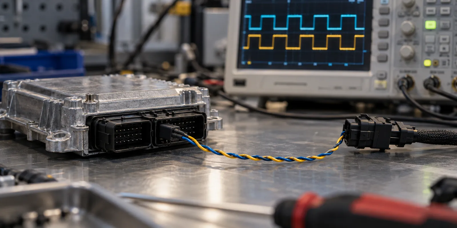
- Two wires work together: High-speed CAN communicates through the voltage difference between CAN High and CAN Low. Twisting the wires helps reduce the effect of electromagnetic interference.
- Termination belongs at the ends: A typical high-speed CAN backbone has a 120-ohm termination at each end. Adding a separate termination to every controller is incorrect.
- Read the voltages together: In a typical high-speed CAN example, both wires sit near 2.5 volts in the recessive state. During a dominant bit, CAN High rises toward 3.5 volts while CAN Low falls toward 1.5 volts. These are illustrative levels; measurements must be assessed against the transceiver's specifications.
- The identifier distinguishes messages: The CAN identifier also contributes to message priority. It should not automatically be treated as the address of a particular controller.
- Length and payload are separate: Classical CAN carries up to eight data bytes. Separating the identifier, length, and payload is the first step in understanding a log entry.
- Raw bytes do not explain themselves: Interpreting a value as speed, temperature, or another signal requires message definitions. A byte sequence cannot be assigned a definitive meaning without a DBC file or suitable manufacturer documentation.
My main takeaway is that a healthy-looking signal alone does not prove that we have interpreted its messages correctly. Diagnosing a problem starts on firmer ground when the physical network and the data definitions are examined together.
Related video: @ridakworks